
Why Choose a Pneumatic Valve for Industrial Automation?
Why Choose a Pneumatic Valve for Industrial Automation?
A pneumatic valve controls compressed air with remarkable speed, repeatability, and practical simplicity. In a packaging line, it can direct air to a cylinder within milliseconds. That movement may push cartons, clamp parts, or separate products without electric motors at every station. This makes pneumatic technology attractive for factories demanding frequent cycles and dependable operation.
Compressed-air efficiency expert Ron Marshall has warned, “Compressed air is not free.” That sentence deserves attention. A pneumatic valve needs clean, dry air, correct pressure, and careful maintenance. Otherwise, leaks can increase energy costs, while moisture may damage internal components. The technology is efficient, but only when engineers design the complete air system properly.
A well-selected valve can tolerate demanding industrial environments, including dust, vibration, and regular washdown. Stainless-steel bodies and suitable seals can support food-processing or chemical applications. Response time, flow rate, port size, and operating temperature still require close evaluation. Small errors matter.
ISO 4414 guidance helps engineers address pneumatic safety and system design. Experienced technicians also inspect tubing, silencers, regulators, and exhaust paths during commissioning. These details are easy to overlook. They should not be.
The strongest reason to choose a pneumatic valve is balance. It offers fast actuation, compact installation, and straightforward troubleshooting. However, it is not automatically the cheapest solution. Electricity, air preparation, noise, and maintenance influence its real cost. A careful comparison should come before purchase. That is where many automation projects become more reliable—or quietly become expensive.
What Is a Pneumatic Valve? ISO 4414 and Its Industrial Safety Framework
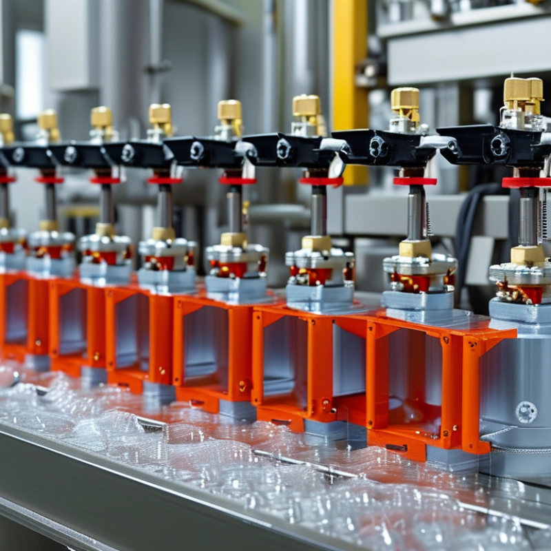
A pneumatic valve directs compressed air to start, stop, or regulate machine movement. It may control a cylinder, clamp, gripper, or lifting mechanism. At 6 bar, even a small actuator can create serious crushing force. That is why ISO 4414 matters. This standard provides a safety framework for pneumatic systems, from design and installation to operation and maintenance. It encourages risk assessment, clear controls, pressure limitation, and safe energy isolation.
A compliant design should let technicians shut off the air supply and release trapped pressure. Exhaust ports need suitable protection, especially near dusty work areas. Valves should match the required pressure, flow, temperature, and response time. During commissioning, test every stop function with the machine unloaded first. Then verify the result under realistic conditions. A checklist helps, but it is not perfect. A hidden hose failure or poorly labeled isolator can still create danger. Human factors deserve equal attention.
Tips: Mark every isolation point clearly. Fit gauges where pressure must be checked. Confirm that exhaust air cannot strike workers. Inspect tubing for cuts, swelling, and loose fittings. Train operators to report unusual noise or delayed movement. Never assume a quiet valve is a safe valve. Small oversights often become expensive lessons.
Why Choose a Pneumatic Valve for Industrial Automation? — What Is a Pneumatic Valve? ISO 4414 and Its Industrial Safety Framework
| Data Dimension | Factual Data | Industrial Automation Relevance |
|---|---|---|
| Basic Definition | A pneumatic valve controls, directs, or regulates the flow of compressed air or another approved gas within a pneumatic circuit. | It manages actuator movement, sequencing, clamping, gripping, lifting, and air isolation. |
| Operating Medium | Usually filtered and conditioned compressed air. Air quality, pressure, and lubrication requirements depend on the valve and system design. | Proper air preparation helps reduce contamination, corrosion, sticking, and premature wear. |
| Common Valve Configurations | 2/2 valves have two ports and two positions; 3/2 valves have three ports and two positions; 4/2 and 5/2 valves are commonly used to control double-acting cylinders. | The port and position arrangement determines how air is supplied, exhausted, and switched between actuator chambers. |
| Actuation Methods | Typical methods include solenoid actuation, pneumatic pilot actuation, manual override, mechanical actuation, and spring return. | The selected method affects response, control architecture, troubleshooting, and behavior during loss of power or air. |
| Typical Control Functions | Functions include on/off isolation, directional control, pressure regulation, flow control, soft start, quick exhaust, and pressure relief. | These functions support automated motion control and help manage pneumatic energy in a machine. |
| Response and Repeatability | Pneumatic valves can provide rapid switching, but actual response depends on valve design, air pressure, tubing length, flow capacity, load, and exhaust conditions. | Correct sizing and short, appropriately sized pneumatic lines improve cycle consistency and reduce delays. |
| Energy and Utility Considerations | Compressed air is convenient and clean at the point of use, but generating, treating, and distributing compressed air consumes energy. | Leak management, appropriate pressure settings, efficient components, and scheduled maintenance can reduce operating costs. |
| ISO 4414 Scope | ISO 4414 provides general rules and safety requirements for pneumatic fluid power systems and their components used on machinery. | It provides a framework for designing, installing, operating, maintaining, and modifying pneumatic systems safely. |
| Risk Assessment Principle | Safety measures should be selected based on the hazards, operating conditions, foreseeable misuse, and maintenance activities of the complete machine. | A valve should not be evaluated in isolation; the complete circuit and machine control system must be considered. |
| Stored Pneumatic Energy | Air trapped in valves, cylinders, hoses, accumulators, or chambers can continue to create movement or force after the supply is disconnected. | Isolation, lockout, controlled exhaust, and verification of zero residual pressure are essential before servicing. |
| Emergency Stop Behavior | An emergency stop strategy must define how pneumatic energy is isolated, exhausted, retained, or controlled for the specific hazard. | The safest valve arrangement depends on whether the machine requires stopping, holding, lowering, or controlled release of motion. |
| Fail-Safe Considerations | Spring-return, center-position, redundant, or monitored arrangements may be used depending on the assessed risk and required safe state. | Loss of electrical power or compressed air does not produce one universal result; the circuit must be engineered for the intended safe response. |
| Installation Requirements | Piping and components should be selected, connected, supported, protected, and identified to prevent incorrect assembly and unintended release of energy. | Good installation practice improves reliability, simplifies maintenance, and reduces the likelihood of hose whip or accidental disconnection. |
| Maintenance and Inspection | Maintenance should include checking leaks, fittings, tubing, valve operation, pressure settings, exhaust devices, filters, and safety functions. | Regular inspection helps maintain predictable actuator behavior and preserves the effectiveness of protective measures. |
| Documentation and Identification | Pneumatic schematics, component identification, operating instructions, maintenance procedures, and safety information should be available for the system. | Clear documentation supports commissioning, fault diagnosis, training, safe modification, and controlled maintenance. |
Related Posts
-
How to Select the Best Pneumatic Valve for Your Industrial Applications
-

Top Strategies for Enhancing Efficiency with Pneumatic Valves in Industrial Applications
-

Top 10 Pneumatic Valve Types for Optimal Performance in Industrial Applications
-
Exploring the Impact of Motorized Valve Technology on Energy Efficiency in Industrial Applications
-
How to Choose the Right Ball Check Valve for Your Industrial Needs
-

What Defines an Actuated Ball Valve and Its Importance in Industrial Applications